For detailed description of the HIPPIE optical design and performance, please see the beamline publication:
HIPPIE: a new platform for ambient pressure X-ray photoelectron spectroscopy at the MAX IV Laboratory
Zhu, S., Scardamaglia, M., Kundsen, J., Sankari, R., Tarawneh, H., Temperton, R., Pickworth, L., Cavalca, F., Wang, C., Tissot, et al. (2021). J. Synchrotron Rad. 28, DOI: https://doi.org/10.1107/S160057752100103X
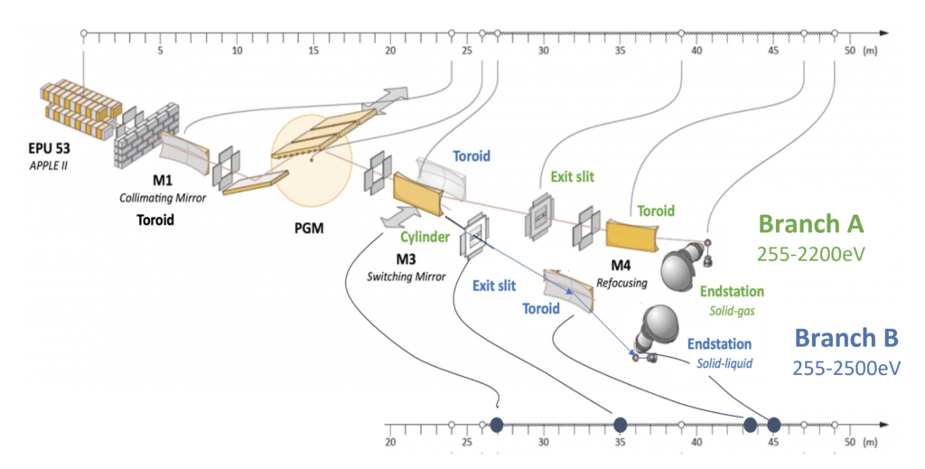
Hippie is a soft X-ray beamline designed to deliver high-intensity photon flux (>1012 ph/s) with exceptional resolution by fully utilising the very low emittance of the 3 GeV ring. The beamline consists of two branches optimised for different energy ranges.
| Branch A (Solid-Gas endstation) | Branch B (Solid-Liquid endstation) | |
| Energy Range | 255 eV – 2000 eV | 255 eV – 2500 eV |
| Polarisation | Horizontal | Horizontal |
| Resolution | up to 35 000 | up to 8000 |
| Photon Flux | > 1012 ph/s (260 – 2000 eV, R=10 000) | >1012 ph/s (1000 – 2200 eV, R=1000) |
| Spot Size | 60 µm (h) x 25 µm (v). Slit-independent | 10 µm (h) x 5-25 µm (v). Vertical size is slit-dependent |
X-ray Source
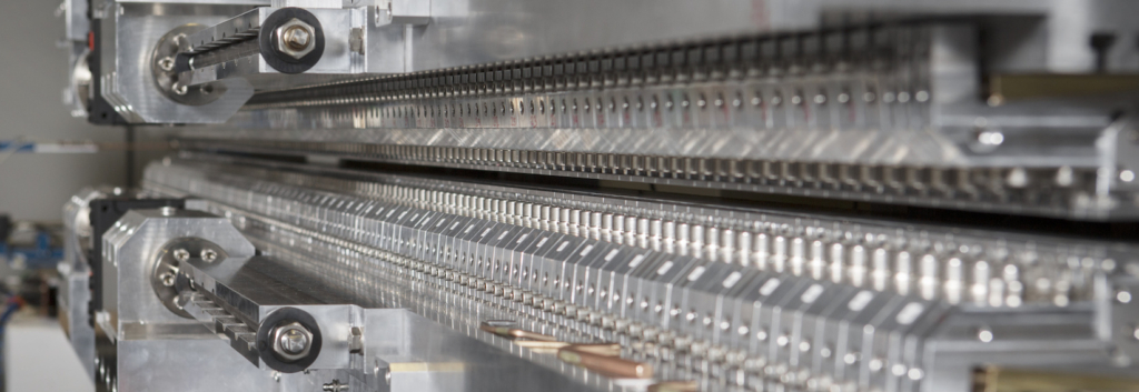
| Type | APPLE II with permanent magnets |
| Period Length | 53 mm |
| Physical Length | 4 m (placed inside 5m straight section) |
| Accessible Polarisations | Linear (inc. Horizontal), Elliptical, Circular |
Beamline Optics
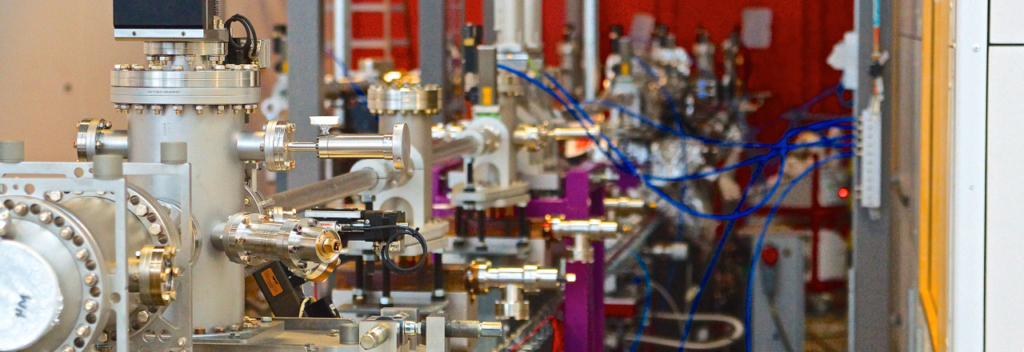
The beamline shares a Collimated Plane Grating Monochromator (cPGM) between two branchlines. Hence only one endstation can be used at the time. Switching between branchlines is done by laterally moving M3 chamber vessel.
The first optical element (M1) in the beamline is a toroidal mirror, which collimates the beam vertically and focuses the beam horizontally onto the exit slit. The cPGM consists of a plane mirror and one or more plane gratings. At the moment one grating (1200 l/mm) in installed covering the entire energy range of the beamline.
The dispersed radiation from the grating is focused horizontally onto the exit slit by the cylindrical (for branch A) or toroid (for branch B) focusing mirror (M3). The focusing mirror at the branch B is of toroid shape to compensate for the manufacturing error in the M1 radius.
The refocusing for both branches is accomplished by a single toroidal mirror (M4). At the branch A the mirror does not image the vertical opening of the exit slit directly, but the vertical image size at the sample plane (2 m from M4) is dictated by the vertical divergence of the beam, which can be controlled by the monochromator. At the Branch B the vertical beam size is dependent on the exit slit opening.
All the mirrors, except for the plane mirror in the monochromator, deflect horizontally – hence, all slope errors and heat load deformations on these mirrors are diminished in the dispersion plane in a well-known manner.
| Optical element | M1 common | M2 common | PG common | M3 Branch A | Exit slit Branch A | M4 Branch A | M3 Branch B | Exit slit Branch B | M4 Branch B |
| Shape | Toroid | Plane | Plane | Cylinder | Rectangle | Toroid | Toroid | rectangle | Toroid |
| Deflection / azimuthal angle | Horizontal /90° | Vertical /0° | Vertical /180° | Horizontal 90° | ‘narrow’ opening in vertical 0-100 µm | Horizontal 90° | Horizontal 90° | ‘narrow’ opening in vertical 20-160 µm | Horizontal 90° |
| Position to proceeding element (mm)(sample BL at mono E = 867 eV ) | 4700 | 1788.89 | 212.059 Vertical offset: 20 mm | 1000 | 12000 | 8000 | 1000 | 8000 | 8500 |
| Distance (m)(along BL) | 24 | variable | 26 | 27000 | 39000 | 47000 | 27 | 35 | 43.5 |
| Incidence Angle | 1° | 0°- 9° | 0°- 12° | 1.5° | 1.5° | 1.5° | 1.5° | ||
| Opt.size (mm), substraite | 320 x 10 | 370 x 10 | 130 x 10 | 120 x 28 | 130×20 | 120x28 | 120x20 | ||
| Geometrical size | 370×60 | 420×60 | 140×25 | 140×40 | 150×40 | 140×40 | 140×40 | ||
| Coating Material | Au | Au | Au | Au | Au | Rh | Rh | ||
| Substrate Material | Si | Si | Si | Si | Si | Si | Si | ||
| Roughness (Å) | 2.53 | 2.1 | 3 | 3 | 3 | 3 | – | 3 | |
| Slope error Sag./Merid. (arcsec) | 0.17/0.43 | 0.03/0.07 | 0.02/0.04 | 0.3/0.3 | – | 0.3/2.5 | |||
| Entrance arm (mm) | 24000 | -/∞ | 8000 | -16037/∞ | 8500 | ||||
| Exit arm (mm) | 15000/∞ | -/12000 | 2000/2025 | 8000 | 1500 | ||||
| Parameters | R=1216580 mmρ=837.6 mm | Blaze angle1.01° N=1200 l/mm Cff=2.25 Aspect angle=172.8° | R= ρ= | R= ρ= | R=1.220 km ρ=418.8 mm | R= 97410 mm ρ=66.75 mm |
Performance
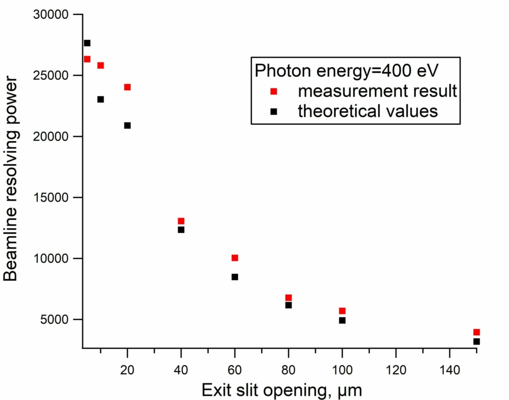
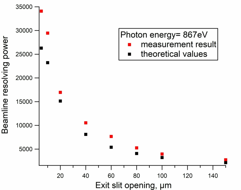
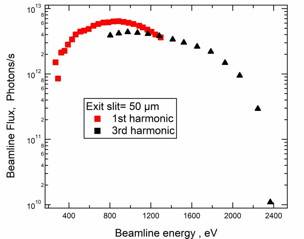
The HIPPIE beamline can achieve 25000-35000 resolving power at 5-10 µ exit slit size. The beamline flux is higher than 1012 ph/s up to 2000 eV with 50 micron exit slits, typical for AP-XPS measurements, where the resolving power is ~10000.
